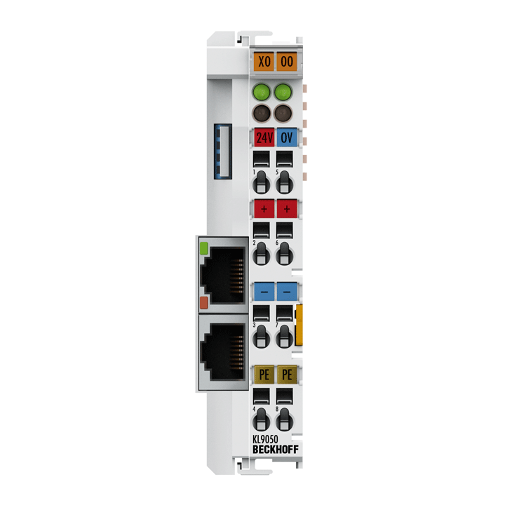
Beckhoff KL9050 Terminal bus extension, coupler terminal
Fiyat
99 €
Beckhoff KL9050 Terminal bus extension, coupler terminal KL9050 | Terminal bus extension, coupler terminal Technical data KL9050 Number of Bus Terminals 64 Current load ≤ 10 A Power LED green Defect LED – Type/number of peripheral signals Bus Coup
Beckhoff KL9050 Terminal bus extension, coupler terminal
KL9050 | Terminal bus extension, coupler terminal
| Technical data | KL9050 |
|---|---|
| Number of Bus Terminals | 64 |
| Current load | ≤ 10 A |
| Power LED | green |
| Defect LED | – |
| Type/number of peripheral signals | Bus Coupler dependency |
| Distance between stations | max. 5 m between KL9050 and KL9050 |
| Bus interface | 2 x RJ45 socket (input + output) |
| Power supply | 24 V DC (-15 %/+20 %) |
| Input current | 70 mA + (total K-bus current)/4, 200 mA max. |
| Starting current | 2.5 x continuous current |
| Current consumption K-bus | typ. 70 mA + (total K-bus current)/4, max. 200 mA |
| Current supply K-bus | up to 400 mA |
| Power contacts | max. 24 V DC/max. 10 A |
| Nominal voltage | 24 V DC (-15 %/+20 %) |
| Electrical isolation | 500 V (power contact/supply voltage/fieldbus) |
| PE contact | yes |
| Shield connection | – |
| Electrical connection to DIN rail | – |
| Special features | coupler terminal for K-bus extension (max. 64 Bus Terminals) |
| Weight | approx. 75 g |
| Operating/storage temperature | 0…+55 °C/-25…+85 °C |
| Relative humidity | 95 %, no condensation |
| Vibration/shock resistance | conforms to EN 60068-2-6/EN 60068-2-27 |
| EMC immunity/emission | conforms to EN 61000-6-2/EN 61000-6-4 |
| Protect. rating/installation pos. | IP20/variable |
| Approvals/markings | CE, UL, ATEX, DNV GL |
| Ex marking | II 3 G Ex nA IIC T4 Gc |
The KL9050 coupler terminal replaces the Bus Coupler on a Bus Terminal block. The KL9050 is the counterpart to the KL9020. The S(F)TP cable (shielded twisted pair) is plugged into the upper socket, providing the logical connection to the Bus Coupler. The extension is fully transparent for the Bus Coupler. All Bus Terminal system functions remain unchanged. The second RJ45 socket allows the system to be extended further. A new KL9050 can be connected to the first coupler terminal. The whole system can thereby be extended by 31 stations. The supply voltage for the field level and the internal electronics can be input separately. Both levels are thereby electrically isolated from one another. In the KL9050 a 400 mA K-bus power supply unit supplies the added Bus Terminals. The internal electronics and the field level can be supplied together from a single voltage source. Three diagnostic LEDs give information about the supply voltage for each Bus Terminal block, internal and field level. The KL9050 can be used as the last coupler terminal in the system or as a bridge between two Bus Terminal blocks. You can switch between these two functions with a selector switch. The switch must be correctly positioned for the system to operate.

 tr
tr  English
 Russian
 العربية
 German
